Getting started
Getting Started with MicroPython on the ESP32
What MicroPython is, how the ESP32 DevKit V1 runs your main.py, the GPIO2 LED, timing, your first LED on a breadboard and the path to a real board.
By Prof. Rodrigo Faustino · Updated on · 16 min read
Metrics for this article
- Words
- 3,064
- Characters
- 17,185
- Reading time
- ~16 min
Every microcontroller board starts the same way: with a blinking LED. It seems like very little, but behind those two lines of code are almost all the ideas you will use from here on — what a pin is, what "output" means, how the program waits for time to pass and how the text you write turns into current in a wire. This article is the map for the start of the journey with MicroPython on the ESP32 DevKit V1, the board that PyPlaca simulates. We will see what runs inside the board, write the first programs, build a real LED on a breadboard and, at the end, see how to take the same main.py to a real ESP32.
All the numbers in this text come from the project's documentation (the hardware documents and the datasheet card of each part) or from the official MicroPython documentation. When a value has not been measured yet on a lab board, PyPlaca says so — and so does this article.
What MicroPython is
Python is a programming language known for being easy to read. It normally runs on a computer with gigabytes of memory and an operating system underneath. MicroPython is a reimplementation of Python 3 made to fit on microcontrollers: small chips, with a few hundred kilobytes of memory, no operating system and built to talk to the physical world — buttons, LEDs, sensors, motors.
The most important difference for someone starting out is where the program runs. With Arduino, for example, you write C++ on the computer, a compiler turns everything into machine code and that code is flashed to the board. With MicroPython, what is flashed to the board just once is the interpreter: MicroPython itself, in a firmware file. After that, the board understands Python. You send text files (main.py, boot.py and your modules) and the interpreter reads and runs them line by line, right there, inside the chip.
This brings two huge advantages for learning. The first is the REPL, the >>> "prompt" that shows up in the serial terminal: you type a line of Python and the board answers right away. You can light an LED by typing Pin(2, Pin.OUT).on() without saving or flashing anything. The second is that errors show up as text, with the line number and the kind of problem, instead of the board simply "doing nothing".
PyPlaca uses MicroPython v1.29.0 as its reference, in the official version for the standard ESP32 (the ESP32_GENERIC firmware). The simulator reproduces the API, the error messages and even the curious details of that version: the idea is that your main.py works the same when it goes to the real board.
From the syllabus to a planned semester
- Teaching plan and calendar built automatically
- Class diary ready to paste into SIGA
- Slides and exercise lists with answer keys
Free Community edition · Windows
The board: ESP32 DevKit V1
The 30-pin DevKit V1 is one of the most common ESP32 boards in school labs. In the middle sits the ESP32-WROOM-32 module, a little metal box with the ESP32 chip (two cores, Wi-Fi and Bluetooth), the flash memory and the antenna drawn on the circuit board itself. Around the module, the DevKit adds what is missing to use the chip easily: the USB connector, the USB-serial converter, the voltage regulator, two buttons and two LEDs.
Some facts about the board that will keep showing up:
- the pins work at 3.3 V. A pin at high level sits at 3.3 V; at low level, at 0 V;
- the maximum voltage a pin tolerates is 3.6 V. Above that the chip can be damaged — which is why 5 V sensors call for care (there is a whole article about that in this series);
- there are 30 pins, 15 on each side. Not all of them are GPIOs: there is the
3V3, theVIN(the 5 V from the USB), twoGNDand theEN, which restarts the board; - the board's blue LED is connected to GPIO2. It is the one the first program blinks;
- the EN button restarts the chip; the BOOT button is connected to GPIO0 and, pressed at power-up, puts the board in firmware flashing mode;
- with MicroPython, the CPU runs at 160 MHz (a value checked on a lab DevKit V1).
The pins appear on the board with names like D2, D18 or D34. The number after the D is the GPIO number (General Purpose Input/Output), and that is the number MicroPython uses. Writing Pin('D2') does not work: the right way is Pin(2). PyPlaca's pinout shows each of the 30 pins with what it can do and the precautions for each.
Pins that need attention
The ESP32 has a few factory rules that catch beginners by surprise. You do not need to memorize them now, but it is worth knowing they exist:
- GPIOs 34 to 39 are input only:
Pin(34, Pin.OUT)givesValueError: pin can only be input. They also have no internal pull resistor; - GPIOs 6 to 11 are used by the module's flash memory and do not even appear on the 30-pin DevKit V1 connector;
- GPIOs 1 and 3 are the REPL's serial port. Using them as ordinary pins shuts the terminal down;
- GPIOs 0, 2, 5, 12 and 15 are strapping pins: the chip reads their level at the instant it powers on to decide how to start. Connecting things that force a level on those pins can keep the board from starting.
The simulator knows these rules and shows an educational warning in the Warnings tab when your program or your circuit runs into one of them, even in cases where the real board would fail silently.
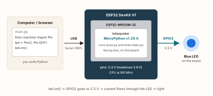
main.py is read by the MicroPython interpreter that lives on the ESP32, and every line moves a real pin.The first program: blinking the GPIO2 LED
To control a pin, MicroPython uses the Pin class, which lives in the machine module (the module that gathers everything hardware-specific). We create an object by giving the pin number and the mode: Pin.OUT for output, Pin.IN for input. Then on() puts the pin at 3.3 V and off() at 0 V.
from machine import Pin
import time

led = Pin(2, Pin.OUT)   # the DevKit V1's blue LED

for i in range(10):
    led.on()
    time.sleep_ms(500)  # half a second on
    led.off()
    time.sleep_ms(500)  # half a second off

print('done: the LED blinked 10 times')Click Open in the simulator and then Run. The code goes to the free IDE's main.py (what was there before comes back with Ctrl+Z) and the simulated board's blue LED blinks ten times. Open the Pins tab: it draws GPIO2 like a logic analyzer, a square wave going up and down every half second.
Notice three details in the code:
from machine import Pinbrings in thePinclass;import timebrings in the time module;Pin(2, Pin.OUT)configures the pin only once, outside the loop. CallingPin(2)again returns the same object (that is how it works in the ESP32's MicroPython), so there is no problem doing it, but no gain either;led.on()andled.off()have equivalents:led.value(1),led.value(0)andled.toggle(), which flips the current level. Use whichever makes the program more readable.
On a real board, a program with while True: runs forever — that is normal on a microcontroller, which exists to do the same task continuously. To stop it, you press Ctrl+C in the terminal (which raises a KeyboardInterrupt) or restart the board. In the simulator, the stop button plays the same role.
Time in MicroPython
The time module has three ways to wait, which differ only in the unit:
time.sleep(1)waits in seconds (it accepts fractions, like0.5);time.sleep_ms(500)waits in milliseconds;time.sleep_us(100)waits in microseconds.
While it waits, the program stays stopped on that line. To measure how much time has passed, MicroPython offers a clock that starts counting when the board powers on: time.ticks_ms(), in milliseconds (there is also time.ticks_us(), in microseconds). The difference between two readings is calculated with time.ticks_diff(fim, inicio) — and not with a simple subtraction.
import time

inicio = time.ticks_ms()
time.sleep_ms(250)
fim = time.ticks_ms()
print('elapsed', time.ticks_diff(fim, inicio), 'ms')

print(10 / 3) # the board uses a 32-bit floatWhy ticks_diff? Because the tick counter wraps around: in the ESP32's MicroPython it counts up to 2^30 milliseconds and starts again from zero, which happens after a little more than twelve days with the board powered on. At that moment, fim - inicio would give an enormous negative number, while ticks_diff does the right calculation. It is a habit worth building from the first program: board time is compared with ticks_diff and added with ticks_add.
The last line of the example shows another difference from the Python on your computer: the ESP32 uses 32-bit floating-point numbers. That is why 10 / 3 shows up as 3.3333332 and not as 3.3333333333333335. That is how a lab DevKit V1 printed it, and the simulator translates, line by line, the MicroPython code that formats numbers so as to show exactly the same text.
The simulator's clock
A fair question: if the simulator runs in the browser, how does it know how long half a second is "on the board"? PyPlaca keeps a virtual clock, the simulation time that appears at the top of the workbench. At 1× speed, it runs together with the real clock. In Turbo, the simulator does not wait: the program finishes almost instantly, but the board's clock keeps counting the right time — a ticks_diff after sleep_ms(250) gives 250 in both modes. This is useful for checking long programs without watching the LED blink.
The AI that remembers your life and lives on your computer
- Long-term memory with the source of every answer
- Works offline: your data stays on your PC
- Reads PDFs, slides, photos and meeting recordings
Essential plan free forever
A real LED on the breadboard
The board's blue LED is handy, but almost every project uses parts outside the board. The next step is to build an LED on a breadboard and connect it to a GPIO. Before connecting any wire, you need to understand two things: the LED and the resistor.
The LED (light-emitting diode) only lets current through in one direction: from the anode (the longer leg, the positive side) to the cathode (the short leg, on the flat-edged side of the body). The other way around, it simply does not light. When it lights, it holds an almost fixed voltage between its legs, the forward voltage (Vf). For 5 mm LEDs, the typical values are about 2.0 V for red, 2.1 V for yellow, 2.2 V for green and 3.1 V for blue and white. The typical maximum current is about 20 mA.
The resistor is what keeps the LED from asking for too much current. Without it, the only things limiting the current would be the internal resistances of the pin and of the LED — too small to protect either one. With a resistor in series, the calculation is simple: the voltage left over on the resistor is the pin's voltage minus the LED's, and the current is that leftover divided by the resistance (Ohm's law).
| LED | Typical Vf | Current with 220 Ω at 3.3 V |
|---|---|---|
| red | ~2.0 V | (3.3 − 2.0) / 220 ≈ 6 mA |
| yellow | ~2.1 V | (3.3 − 2.1) / 220 ≈ 5 mA |
| green | ~2.2 V | (3.3 − 2.2) / 220 ≈ 5 mA |
| blue or white | ~3.1 V | (3.3 − 3.1) / 220 ≈ 1 mA (dim) |
The table shows a common surprise: the blue LED, with the same 220 Ω resistor, is much dimmer. With 3.3 V on the pin, only about 0.2 V is left for the resistor, and the current drops to around 1 mA. It is not a defect — it is the physics of the LED. The simulator shows this effect and, when the current gets very low, warns that the LED is dim.

(3.3 − 2.0) / 220 gives about 6 mA.The breadboard on the inside
The 830-point breadboard is the mounting base for almost every circuit in the series. On the inside, each column has two metal strips: the five holes at the top (a to e) are connected to each other, and the five at the bottom (f to j) too, separated by the middle channel. Along the edges run the + and − power rails, connected along their whole length, which usually carry the supply and the GND. Two legs plugged into the same column (on the same side of the channel) are connected, even with no wire between them — that is how the resistor "touches" the LED.
A practical detail of the DevKit V1: it is wide. Plugged onto an 830-point breadboard, it takes up almost the whole width and leaves only one free row on one side. That is why, in many lab setups (and in the simulator), the board sits next to the breadboard and the pins arrive by wires, or two breadboards are used side by side.
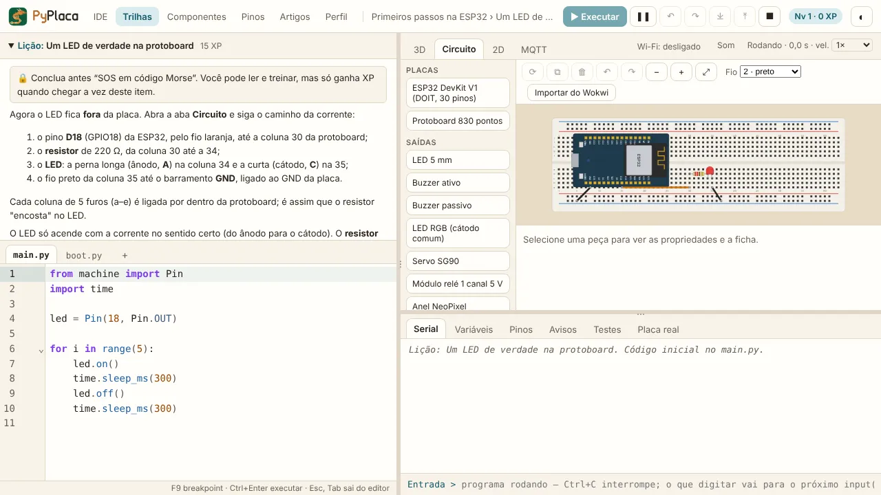
The circuit of the external LED lesson takes this path: from pin D18 (GPIO18) a wire goes to the column of the 220 Ω resistor; the resistor's other leg shares a column with the LED's anode; the cathode sits in a column of its own, connected by a black wire to the GND rail, which in turn is connected to the board's GND. The current leaves the pin, goes through the resistor and the LED and comes back through GND. If any stretch of that path is missing, nothing lights.
from machine import Pin
import time

led = Pin(18, Pin.OUT)

for i in range(5):
    led.on()
    time.sleep_ms(300)
    led.off()
time.sleep_ms(300)This example opens with the circuit already built. Run it and watch the LED blink in the Circuit tab. Then try breaking the circuit on purpose: select the black wire, delete it with Delete and run again. With no path to GND, the LED does not light — exactly like on the bench. Ctrl+Z brings the wire back. Also swap the 220 Ω resistor for a 1 kΩ one in the part panel: the current drops to about a fifth and the LED gets dimmer.
Errors the simulator helps you find
Building circuits is the part where beginners make the most mistakes, almost always for the same reasons. PyPlaca checks the circuit and shows warnings with the name of the problem:
- LED without a resistor: the LED connected straight between the pin and GND. Without a resistor, the current would go past the limit of the LED and of the pin;
- reversed LED: the anode on the lower-voltage side. The long leg goes on the positive;
- short circuit: 3V3 or VIN connected straight to GND. On the real board, the regulator would shut down or burn out;
- disconnected wire: one end of the wire on no pin at all. It does not take part in the circuit and the rest stays incomplete.
Hovering the mouse over a breadboard hole highlights everything connected to it, which helps you see whether two legs really are in the same column. It is the equivalent of following the wire with your finger on the bench.
The board's files: boot.py and main.py
When the ESP32 with MicroPython powers on (or restarts), it looks for two files in its internal file system and runs them in this order: first boot.py, then main.py. The boot.py usually stays almost empty; settings that need to happen before everything else go in it. The main.py is the real program. When main.py ends (or when you interrupt it), the board goes back to the REPL and waits for commands.
The simulator follows the same idea. The IDE project has the main.py and the boot.py, and you can create other .py files to organize the code into modules, importing them normally with import. When the program ends, the Serial panel becomes the REPL, with the >>> prompt, connected to the variables of the program that just ran: you can ask what a variable is worth or call a function without running everything again.
The simulated board's EN button also behaves like the real one: when you release it, the board restarts and runs boot.py and main.py again.
Reading errors the way the board shows them
Errors are part of the process, and MicroPython has the merit of explaining them in text. When something goes wrong, the board prints a traceback: the file, the line and the kind of error. For example, using a variable that does not exist shows NameError: name 'total' isn't defined. The simulator prints exactly the same text as the board (the MicroPython message is a little different from the computer Python's, which says "is not defined") and, right below, an explanation of what usually causes that error.
Some errors every beginner meets on the ESP32:
ValueError: invalid pin: a pin number the chip does not have, such as 24 or 40;ValueError: pin can only be input: trying to use one of GPIOs 34 to 39 as an output;IndentationError: a block with different indentation. In Python, the four spaces at the start of a line are part of the code;ImportError: no module named ...: a module that exists neither in the firmware nor in the project.
Reading the traceback from the bottom up, starting with the kind of error and then the indicated line, solves most cases in a few seconds.
From the simulator to the real board
PyPlaca was designed so that the code leaves the browser and goes to a real ESP32 without changes. What is exported is always the student's Python text: the original main.py, the libraries and the project's modules. The Real board tab gathers the paths:
- Export .zip or Download main.py: to flash with the tool you already use (Thonny, mpremote or another);
- Bill of materials (CSV): the circuit's parts, so you can gather them on the bench;
- Flash to the board: in Chrome or Edge, through Web Serial, the IDE talks to the ESP32 plugged into the USB, writes the files (
main.pylast) and restarts the board to run the new program; - Install MicroPython: for a new board, without the interpreter. The student downloads the official
ESP32_GENERICfirmware, version 1.29.0, from the MicroPython site; the IDE checks that the chip is a standard ESP32 with at least 4 MB of flash, erases the memory, writes the firmware at address0x1000and checks the result before restarting.
On the bench, the circuit's path is the same as on the screen: the same pins, the same resistor, the LED with its long leg on the resistor side. The difference is that, on the real board, a wiring mistake can ruin a part — one more reason to test in the simulator first.
A roadmap for the next steps
With the LED blinking, you have already used the three ideas that support everything else: configuring a pin, changing its level and controlling time. The next articles in this series go deeper into each one:
- GPIO, pull-up and the floating pin: the pin as an input, buttons and why a loose pin is not reliable;
- PWM in practice: brightness, sound and movement with pulse-width modulation;
- The ESP32's ADC: how to measure voltages and why the reading does not reach 3.3 V.
In the tracks, each of these subjects becomes short lessons with a ready-made circuit and challenges with automatic grading. The first track retraces exactly the path of this article, from the board's LED to the first circuit built by you — and ends with a traffic light.